
Client Showcases
We regularly publish project showcases explaining how engineers and technicians have used AllyCAD to overcome challenges and create outstanding designs. We are proud to include such a variety of drawings from hobbyist projects to large scale property developments.
Le Grande Golf Estate
Nel & de Kock Town & Regional Planners are users of AllyCAD and have used the program extensively in all their assignments. The Le Grande Golf Estate is a R550 million estate
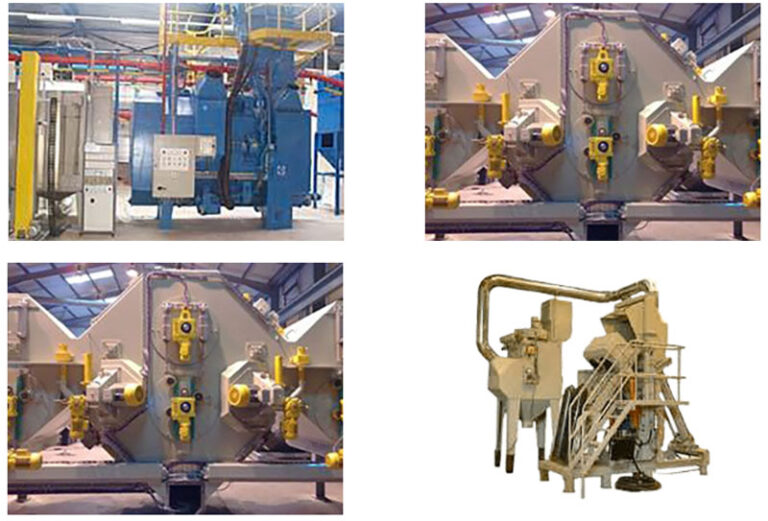
Shot Bast Equipment
J Reid Engineering specialise in the design and manufacture of shotblast equipment with expert knowledge in the supply of compressed air and airless, manual and automatic
Plean Precast
Plean Precast Limited, based near Stirling in Central Scotland UK have been supplying the UK building industry with precast stone and concrete for over 40 years.
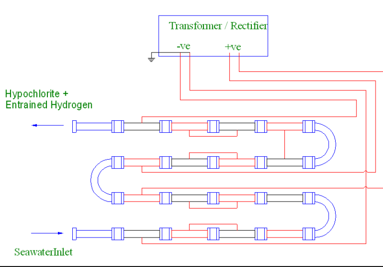
Working With Seawater
AllyCAD permits a CAD user with limited experience to prepare outline drawings which are suitable for speedy translation into more formal documents by the professional designers
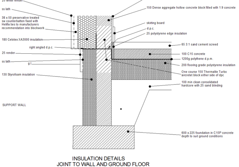
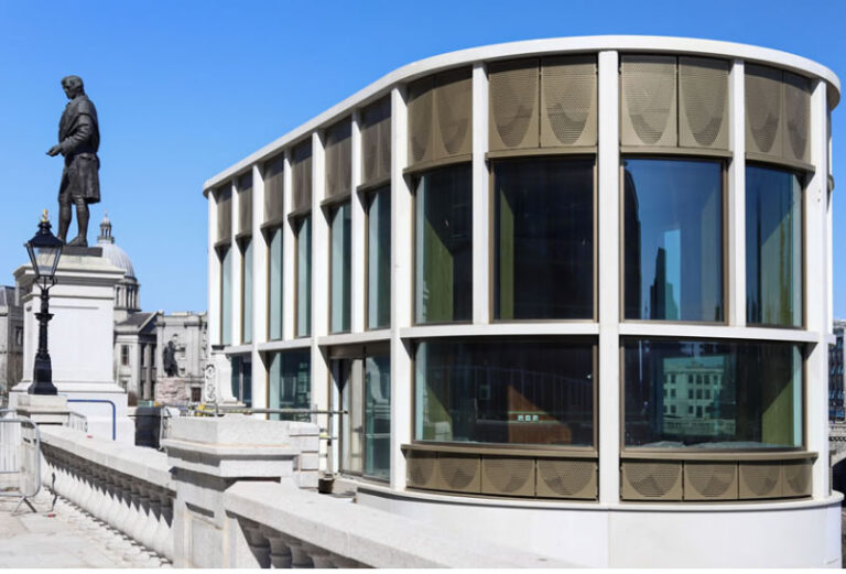
Sustainable Building design
“AllyCAD enabled me to easily provide the extensive detailed drawings of junctions required to execute the work on site to the high standards of air tightness and thermal
Air Conditioning Systems
Norton Air Conditioning design and install all types of air conditioning systems and associated services. Their work involves both the installation of new systems and the
